Fuel-cell Solutions
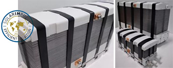
PEM Fuel-cell Stack
Performance PEM Fuel-cell Stacks
- High Power Density
- 1.0kW – 100kW Power Range
- Patented technology
| Product Name | Peak Power (kW) | Voltage Range (V) | Current Range (A) | Dimensions L*W*H(mm) - Stack - Stack + Manifolds |
Mass (KG) (incl.gas manifolds) | Schematic |
|---|---|---|---|---|---|---|
| EH-31 | 1.1 2.2 3.2 4.2 |
5 – 11 10 – 21 14 – 31 19 – 40 |
0-180 | - 200 × 75 × (12 – 50) - 280 × 100 × (90 – 130) |
(4.0 – 8.0) | 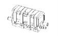 |
| EH-51 | 5.5 12.0 16.0 |
17 – 36 36 – 76 49 – 105 |
0 – 300 | - 280 × 140 × (45 – 146) - 280 × 200 × (140 – 240) |
(10 – 19) | 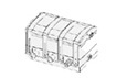 |
| EH-81 | 22 37 68 104 |
36 – 95 62 – 160 112 – 294 172 - 450 |
0 - 450 | - 400 × 120 × (95 – 450) - 480 × 128 × (210 – 580) |
(28 – 75) | 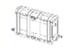 |
Operating Conditions
| Stream | Cathode | Anode | Coolant |
|---|---|---|---|
| Quality | Filtered, no impurities | Grade ≥ 2.5 | DI water, DI + anti-freeze |
| Inlet Temp. (℃) | 65 – 70 | 65 - 70 | 65 - 70 |
| Outlet Temp. (℃) | 76 – 80 (85 short run) | 76 - 80 | As cathode |
| ΔT (℃) | - | - | 8 - 10 |
| RH (%) – No condensation | 35 - 80 | 35 - 80 | - |
| Stoichiometry (λ) | 1.5 - 2.0 | 1.2 - 1.8 | - |
ENGINEERING SERVICE FOR FUEL-CELL INTEGRATION
- Stack Design
- CFD / FEA Simulations
- Process Simulations
- Pinch Analysis
- FC Application